Edges create spectra
A digital fundamental is not its highest emission frequency.Shorter rise time extends the harmonic envelope; part substitution, drive strength, and damping can change compliance results.
The core reference establishes a common language through edges, return paths, differential and common mode, reflections, crosstalk, and high-frequency component models.
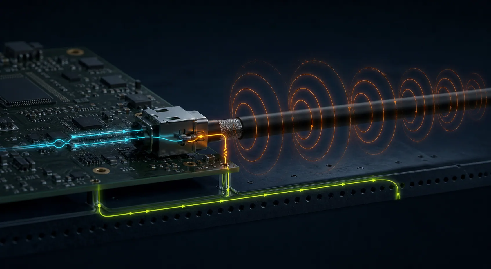 DIFFERENTIAL IMBALANCE → COMMON-MODE CURRENT
These concepts span power, digital interfaces, ESD, shielding, and testing, forming the physical basis for later design decisions.
Shorter rise time extends the harmonic envelope; part substitution, drive strength, and damping can change compliance results.
High-frequency return current follows the lowest-impedance path near the signal; splits and poorly designed layer transitions enlarge the loop.
Confining the field, preserving reference continuity, and controlling geometry is more physical than treating a trace in isolation.
Differential imbalance, parasitic capacitance, and shared impedance transfer board energy to external cables and structures.
A component may become ineffective in another band; filtering and protection require real parasitic models and layout validation.
The same energy chain can explain radiated emissions, interface resets, and transient failures; only source, coupling impedance, and victim change.
The return current detours 80 mm around a plane gap; the same geometry becomes electrically larger as frequency rises.
An estimate is not a compliance verdict, but it reveals which harmonics matter and why component-lot changes create risk.
Use fedge ≈ 1/(πTr) to estimate the trapezoidal edge-spectrum breakpoint. It is not a hard cutoff; package, drive impedance, ringing, and duty cycle alter the measured spectrum.
EMC capability is not memorizing more answers; it is the ability to advance through energy paths and evidence in an unfamiliar system.
Spectrum · dv/dt · di/dt · operating mode
Signal path · return path · parasitic capacitance · chassis
Common-mode current · loop area · seams · harness
Edge control · filtering · shielding · isolation · clamping
Near field · current probe · LISN · chamber · regression