EMC MICRO CLASS / VISUAL LEARNING

Turn electromagnetic fields into actionable intuition.

Start with Maxwell's equations and connect fields, regions, current modes and EMC components into one engineering thread you can observe, manipulate and verify.

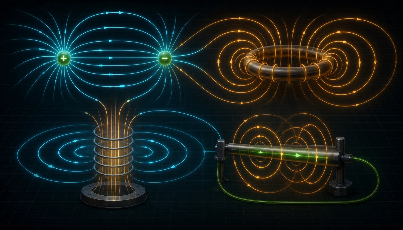
电通量、闭合磁通、感应电场与电流激发磁场的麦克斯韦方程概念图MAXWELL FIELD SYSTEMConceptual illustration · not simulation · AI-assisted technical review complete
LESSON MAPMAXWELL → FIELD → MODE → COMPONENT → PROOF
01 / MAXWELL'S EQUATIONS

Four equations describe one electromagnetic system.

In macroscopic differential form, the equations relate D to free charge, B to flux continuity, changing B to circulating E, and conduction plus displacement current to circulating H. They are not four isolated rules.

麦克斯韦方程描述的电通量、闭合磁通与电磁感应概念图MAXWELL FIELD VIEWConceptual illustration · not simulation · AI-assisted technical review complete
ONE SYSTEM / FOUR LOCAL LAWS

What do Maxwell's equations answer in EMC?

They connect charge, current and time-varying fields. EMC design asks where energy originates, which field and conductor paths couple it, and where it becomes radiation or a disturbing voltage.

∇·D = ρfCharge and electric-flux boundary
∇·B = 0Magnetic flux must close
∇×E = −∂B/∂tChanging B creates circulating E
∇×H = Jf + ∂D/∂tCurrent and changing D create H
MAXWELL / FOUR LOCAL LAWS

Changing magnetic flux creates a circulating electric field

∇×E = −∂B/∂t

Changing flux through a loop induces voltage—the common physical basis of transformers, loop crosstalk and magnetic-field immunity.

02 / ELECTRIC FIELD ↔ MAGNETIC FIELD

Read electric fields through dv/dt; magnetic fields through di/dt and loop geometry.

E and H are coupled in a complete electromagnetic problem, but close to a source either capacitive geometry or a current loop may dominate. Near-field localization therefore requires the appropriate probe.

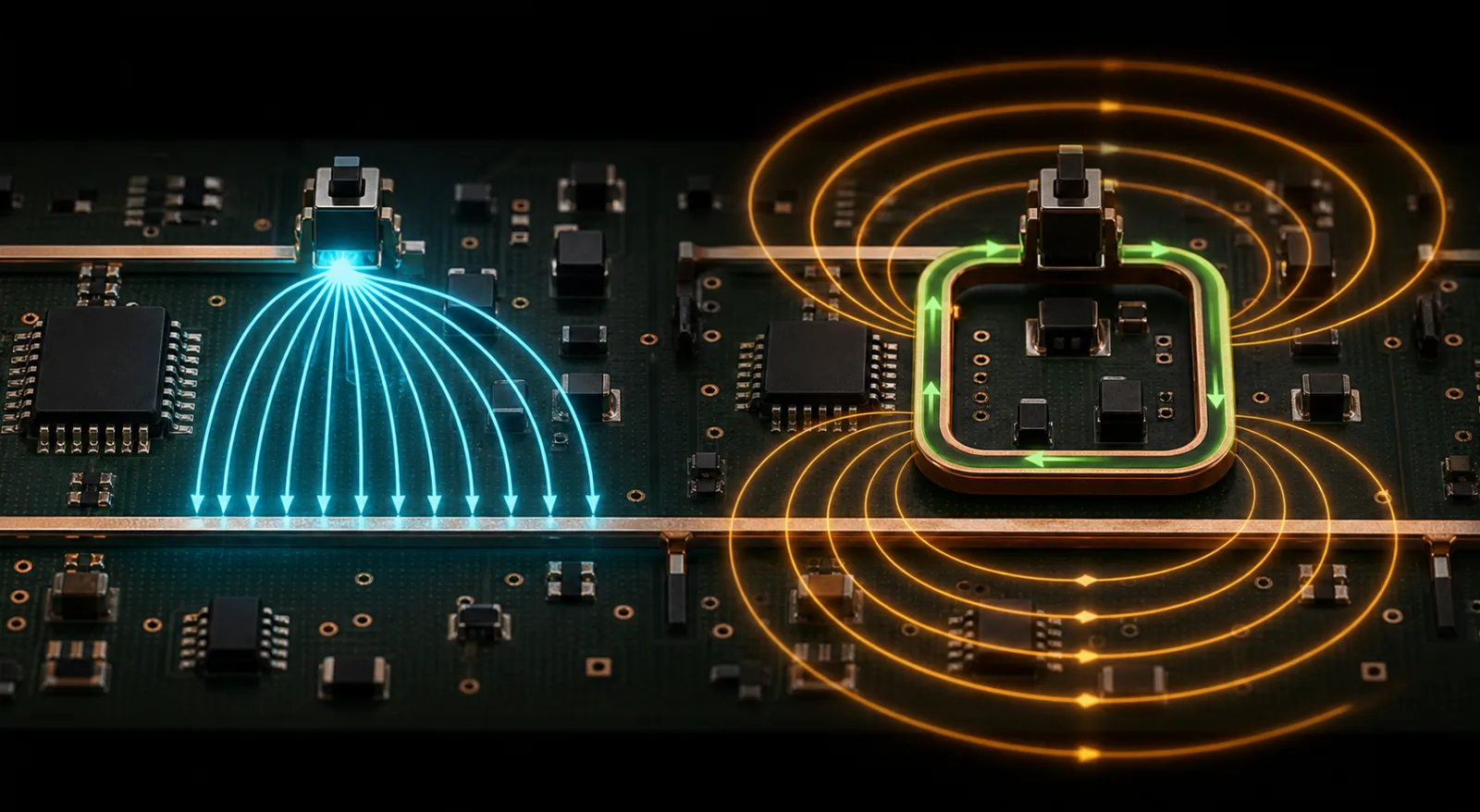
PCB 上高 dv/dt 节点的电场耦合与高 di/dt 回路的磁场耦合对比图E-FIELD / H-FIELD PATHSConceptual illustration · not simulation · AI-assisted technical review complete
SOURCE GEOMETRY DECIDES THE LOCAL FIELD

Identify the source geometry before choosing the measurement.

High-impedance, high-dv/dt nodes tend to produce electric-field problems; large high-di/dt loops tend to produce magnetic-field problems. E and H probes provide different coupling evidence.

Electric field EVoltage, spacing, area and dielectric geometry
Magnetic field H / BCurrent, loop area and relative orientation
ELECTRIC FIELD ↔ MAGNETIC FIELD

Voltage transitions couple through parasitic capacitance

Electric coupling is driven by high dv/dt, high impedance, larger facing area and smaller spacing. Shielding must provide a defined path for displacement current.

03 / NEAR FIELD → FAR FIELD

Near and far fields are not two regions separated by a fixed distance.

Close to a source, geometry controls the E/H ratio. In the far field, E, H and propagation direction form a stable relationship. The boundary varies with wavelength, radiator size and distance.

FIELD REGION / BOUNDARY ESTIMATE

Move the probe to reveal field-region transitions.

This engineering estimate uses λ/(2π) for the reactive scale of a compact source and 2λ or 2D²/λ for the far-field boundary according to radiator size. Real antennas and sites change the result.

04 / DIFFERENTIAL MODE → COMMON MODE

Differential mode carries the signal; asymmetry creates common mode.

Differential and common mode describe current combinations, not cable types. Both modes can coexist on one conductor pair, and asymmetry in connectors or references converts between them.

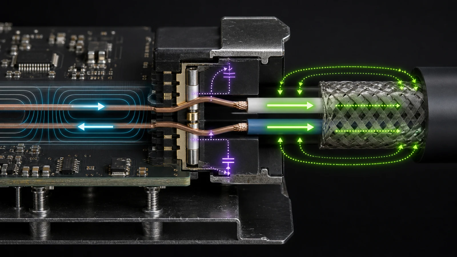
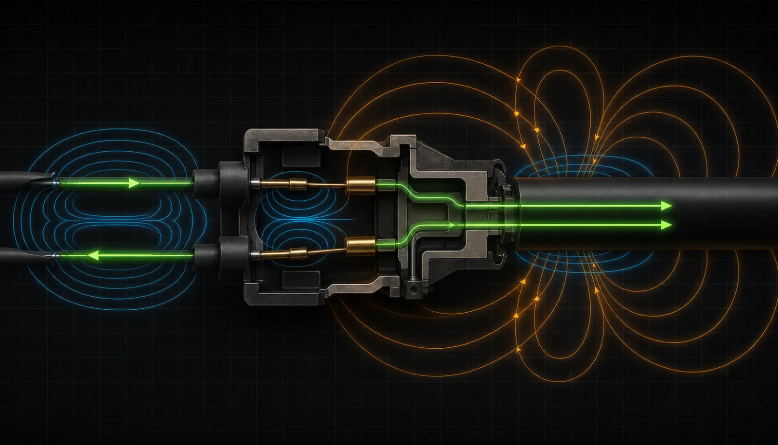
平衡差分电流经过不对称连接器后转换为同向共模电流的概念图MODE CONVERSIONConceptual illustration · not simulation · AI-assisted technical review complete
CURRENT DIRECTION IS THE KEY

Opposite directions form differential mode; the same direction forms common mode.

The external fields of ideal differential current partly cancel. In-phase net current returns through the enclosure, planes, environmental capacitance or a person, and may efficiently excite cable radiation.

Differential mode IDEqual magnitude, opposite directions
Common mode ICMAverage in-phase component
DIFFERENTIAL → COMMON MODE

Balanced differential fields partly cancel at distance.

Equal and opposite conductor currents partly cancel magnetic fields and far-field radiation where geometry permits.

05 / EMC COMPONENTS

Components are not answers; they are tools for controlling paths.

Common-mode chokes, ferrites, feedthrough capacitors, TVS devices, RC snubbers and shielding gaskets act on different energy, frequency, mode and physical boundaries. Their placement and return paths determine whether they work.

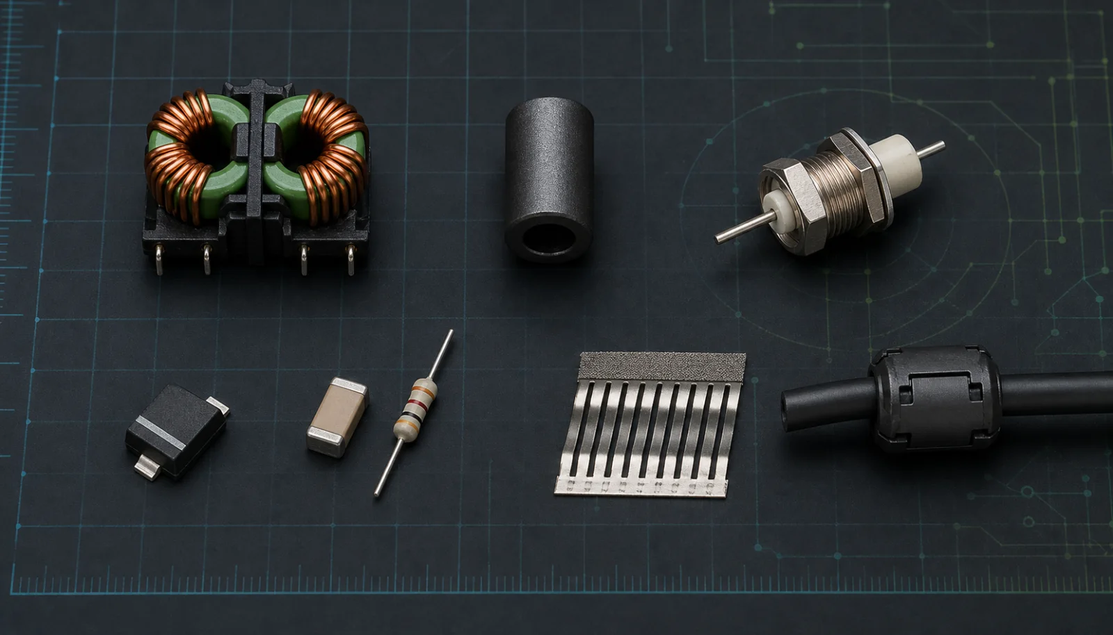
共模扼流圈、磁珠、穿心电容、TVS、RC 元件、屏蔽衬垫和夹扣磁环的实物图COMPONENT GEOMETRYConceptual illustration · not simulation · AI-assisted technical review complete
SOURCE / PATH / BOUNDARY / VICTIM

First identify the current you need to control.

A component name or single-point rating is insufficient. Target mode, impedance curve, DC bias, parasitic inductance, installation boundary and return geometry determine its real behaviour in the product.

ImpedanceFerrites and chokes raise impedance for the target mode
DiversionCapacitors divert RF current at the correct boundary
Clamp / dissipateTVS and RC networks manage transient or ringing energy
Preserve continuityGaskets carry surface current across seams
EMC COMPONENTS / PATH CONTROL

Understand every component in the complete current path.

06 / GRAPHIC RESOURCE LIBRARY

Twelve visuals connect fields, modes and design paths.

Every visual is identified as conceptual and states its boundary. Use them for learning, design reviews and troubleshooting—not as a substitute for simulation or calibrated measurement.

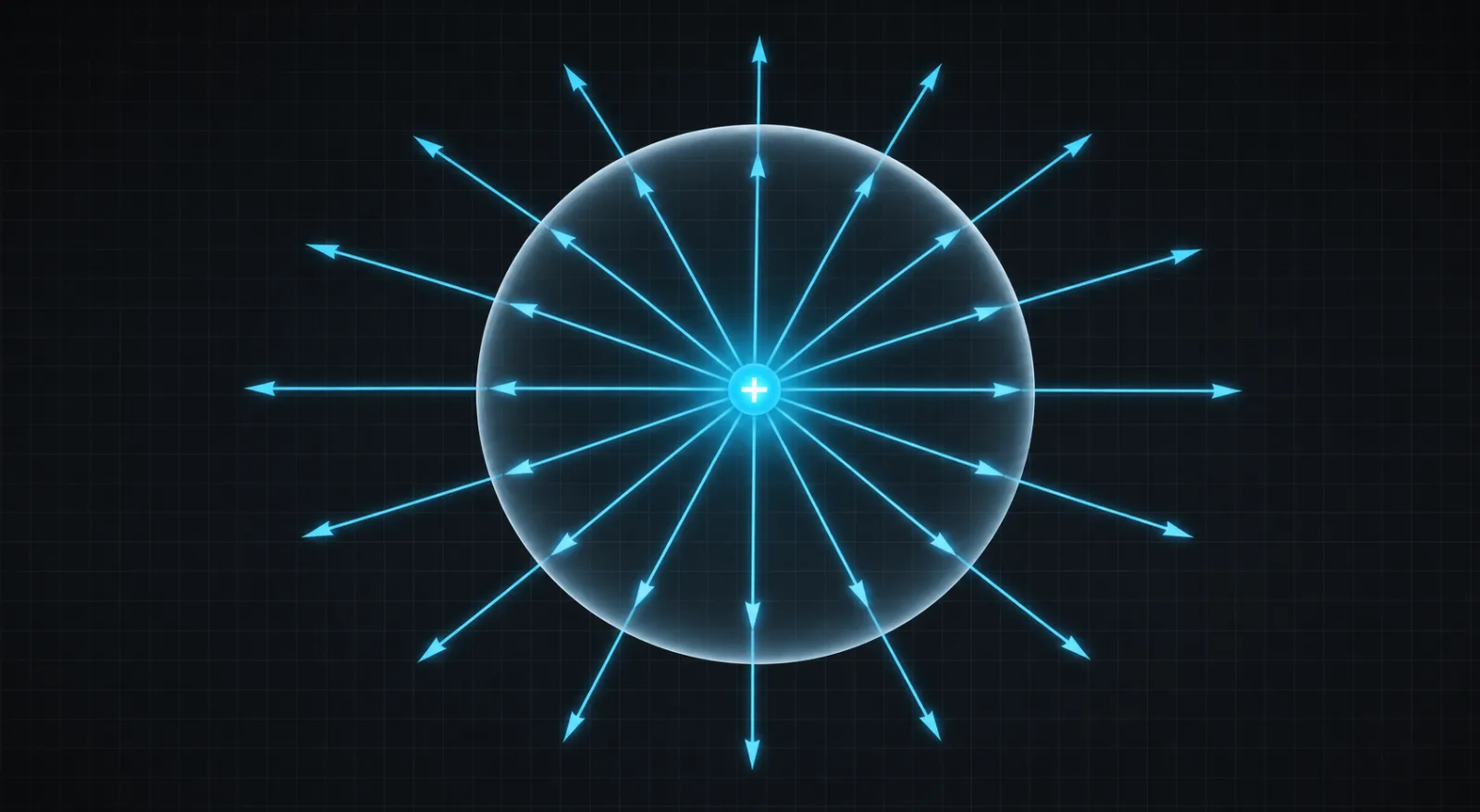
正电荷位于闭合高斯面内,电通量线均匀向外穿过曲面的概念图Conceptual illustration · not simulation · AI-assisted technical review complete
M01 / Maxwell

Charge and electric flux

Positive charge establishes outward electric-displacement flux; net flux through a closed surface corresponds to enclosed free charge.

BoundaryConceptual geometry, not field-strength distribution in a real dielectric.
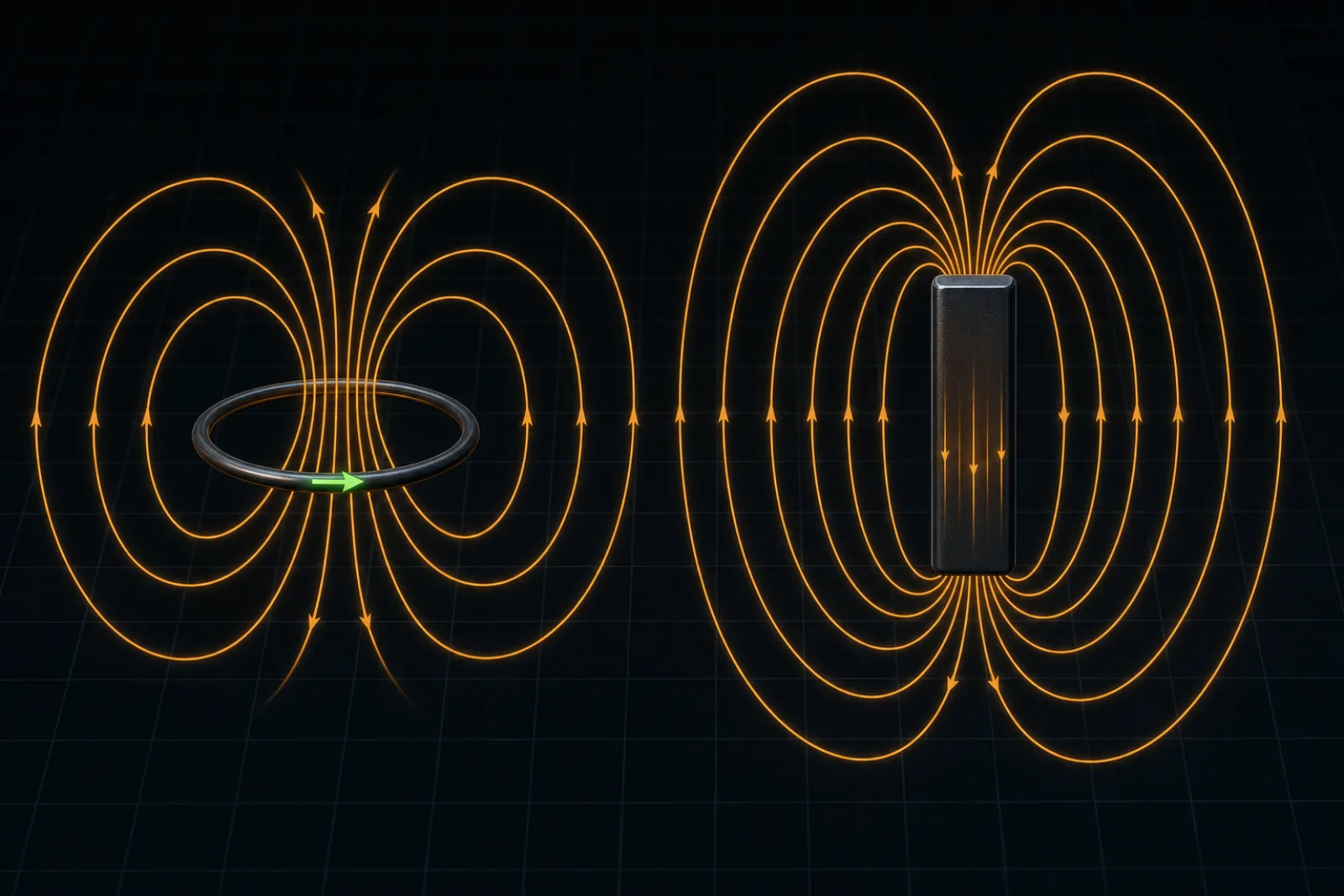
电流环和磁性结构周围形成闭合磁通回路的概念图Conceptual illustration · not simulation · AI-assisted technical review complete
M02 / Maxwell

Magnetic flux always closes

Magnetic flux around a current loop or magnetic structure forms a continuous closed path.

BoundaryLine density expresses topology, not magnetic flux density.
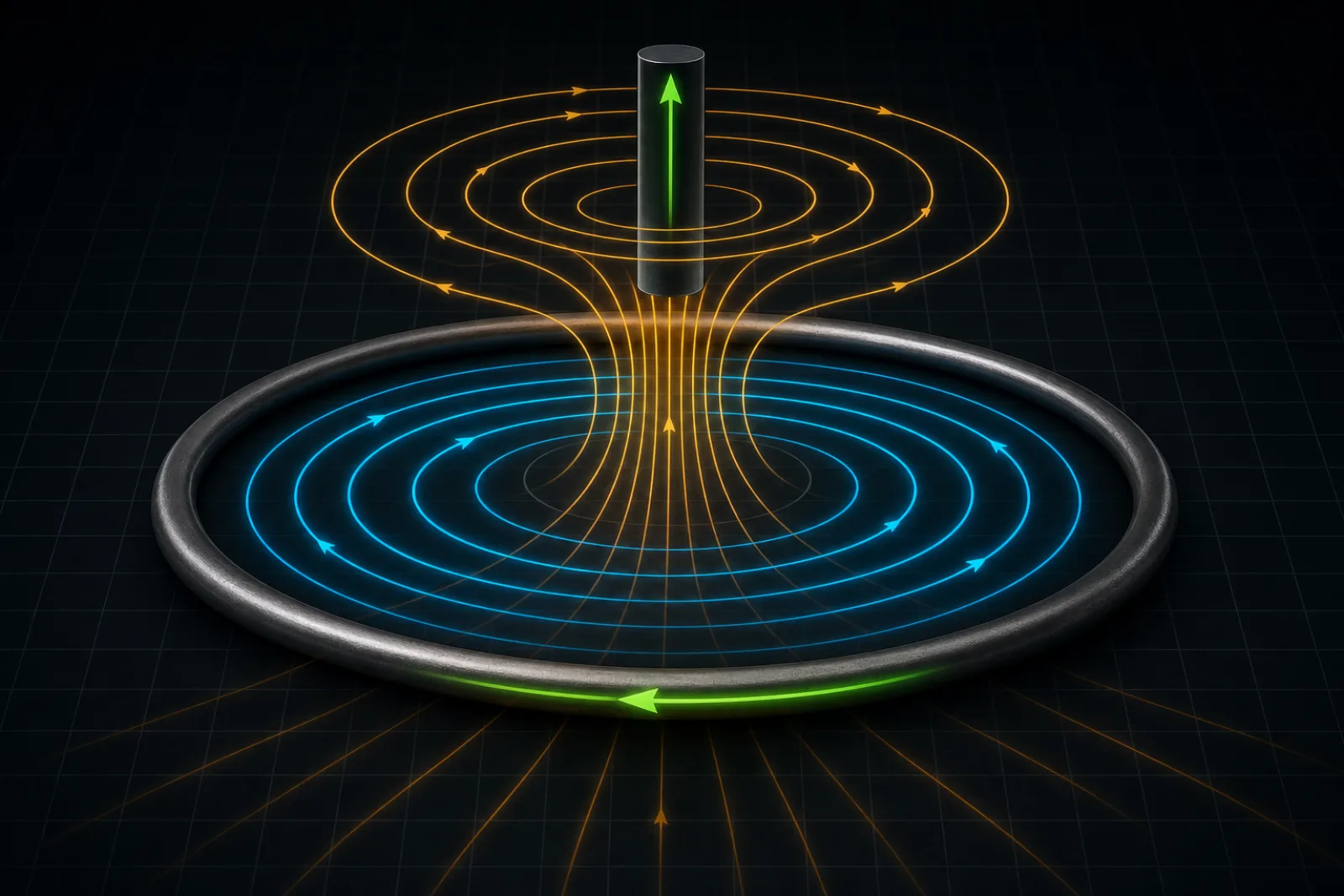
变化的轴向磁通穿过导体环并产生闭合感应电场的概念图Conceptual illustration · not simulation · AI-assisted technical review complete
M03 / Maxwell

Changing flux creates circulating E

Changing magnetic flux through a conductor loop establishes a closed induced electric field and drives induced current.

BoundaryCurrent direction still depends on flux change and Lenz's law.
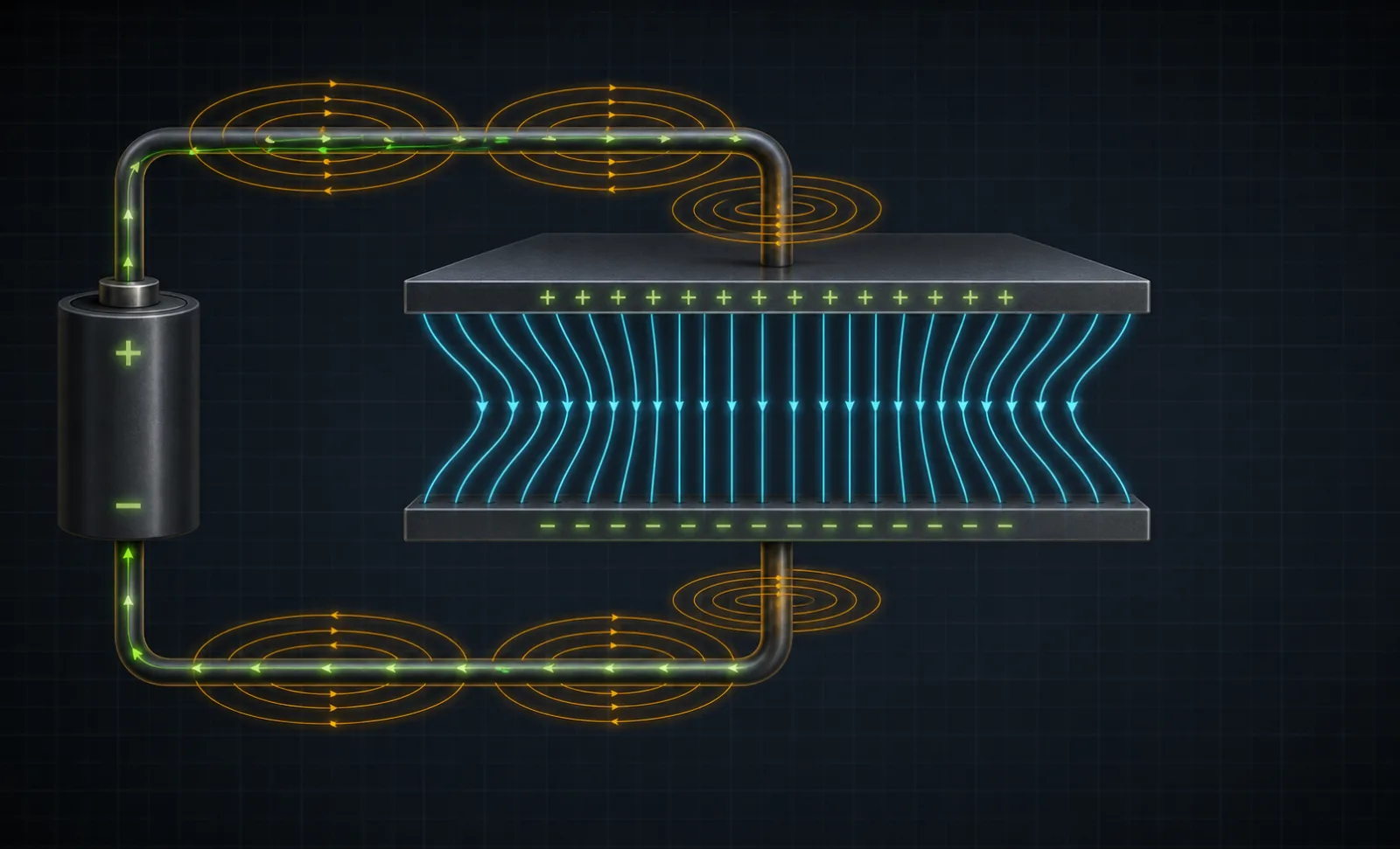
电容充电回路中导电电流、位移电流和环绕磁场连续的概念图Conceptual illustration · not simulation · AI-assisted technical review complete
M04 / Maxwell

Displacement current preserves field continuity

During capacitor charging, changing electric displacement joins external conduction current in establishing the surrounding magnetic field.

BoundaryFringing fields and material dispersion are omitted.
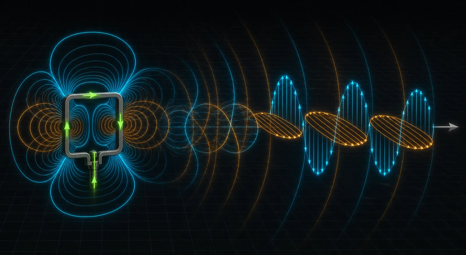
紧凑环路源附近的反应场逐渐转换为远场传播波的概念图Conceptual illustration · not simulation · AI-assisted technical review complete
F01 / Fields and modes

From reactive near field to propagating wave

Stored field energy dominates near the source; with distance, transverse E and H develop into a propagating field structure.

BoundaryRegion boundaries depend on wavelength, source size and distance.
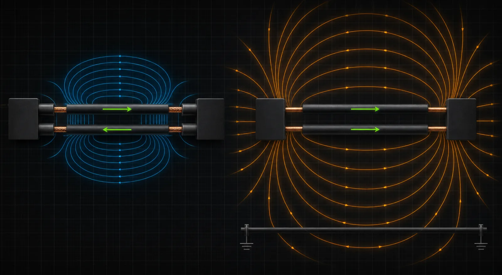
相反方向差模电流与相同方向共模电流及外部场的对比图Conceptual illustration · not simulation · AI-assisted technical review complete
F02 / Fields and modes

Differential- and common-mode current directions

Opposite differential currents partly cancel; in-phase common-mode current needs a remote return path and creates a larger external field.

BoundaryReal channels normally contain both modes.
差分对通过不对称连接器后产生共模电流的剖面概念图Conceptual illustration · not simulation · AI-assisted technical review complete
F03 / Fields and modes

Connector asymmetry creates mode conversion

An asymmetric pin, reference or parasitic structure converts part of differential current into an in-phase cable component.

BoundaryConfirm common-mode amplitude with mixed-mode S-parameters or current measurement.
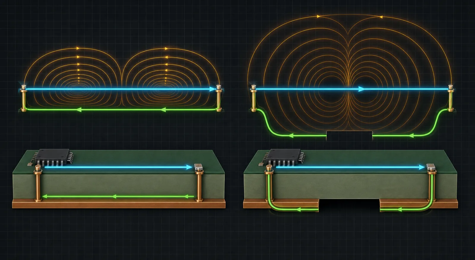
连续参考平面与跨缝信号的返回路径和回路面积对比图Conceptual illustration · not simulation · AI-assisted technical review complete
D01 / Design paths

Reference continuity controls loop area

A continuous plane keeps return current near the signal; a plane split forces detour and enlarges the magnetic loop.

BoundaryField lines compare paths and do not represent emission amplitude.
真实电容在低频、自谐振和高频寄生电感主导状态下的路径对比图Conceptual illustration · not simulation · AI-assisted technical review complete
D02 / Design paths

A capacitor stops being ideal above self resonance

Capacitance dominates at low frequency, impedance is lowest near self resonance, and package plus mounting inductance dominate above it.

BoundaryUse the real impedance curve including layout parasitics.
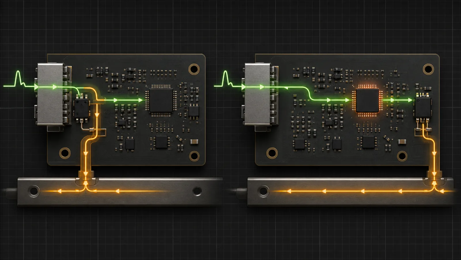
TVS 靠近接口与远离接口时 ESD 泄放路径的对比图Conceptual illustration · not simulation · AI-assisted technical review complete
D03 / Design paths

TVS placement defines the discharge strategy

A TVS at the entry intercepts pulse current into a short return; a remote TVS lets it cross sensitive PCB regions first.

BoundaryResidual voltage also depends on dynamic device behaviour and loop inductance.
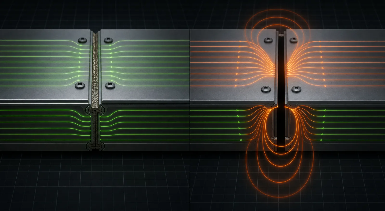
可靠导电搭接与高阻抗屏蔽接缝周围表面电流和泄漏场对比图Conceptual illustration · not simulation · AI-assisted technical review complete
D04 / Design paths

Seam impedance controls shield leakage

Conductive gasketing and dense bonds preserve surface current; a long high-impedance seam produces a stronger leakage field.

BoundaryPerformance also depends on polarization, frequency, seam length and source position.
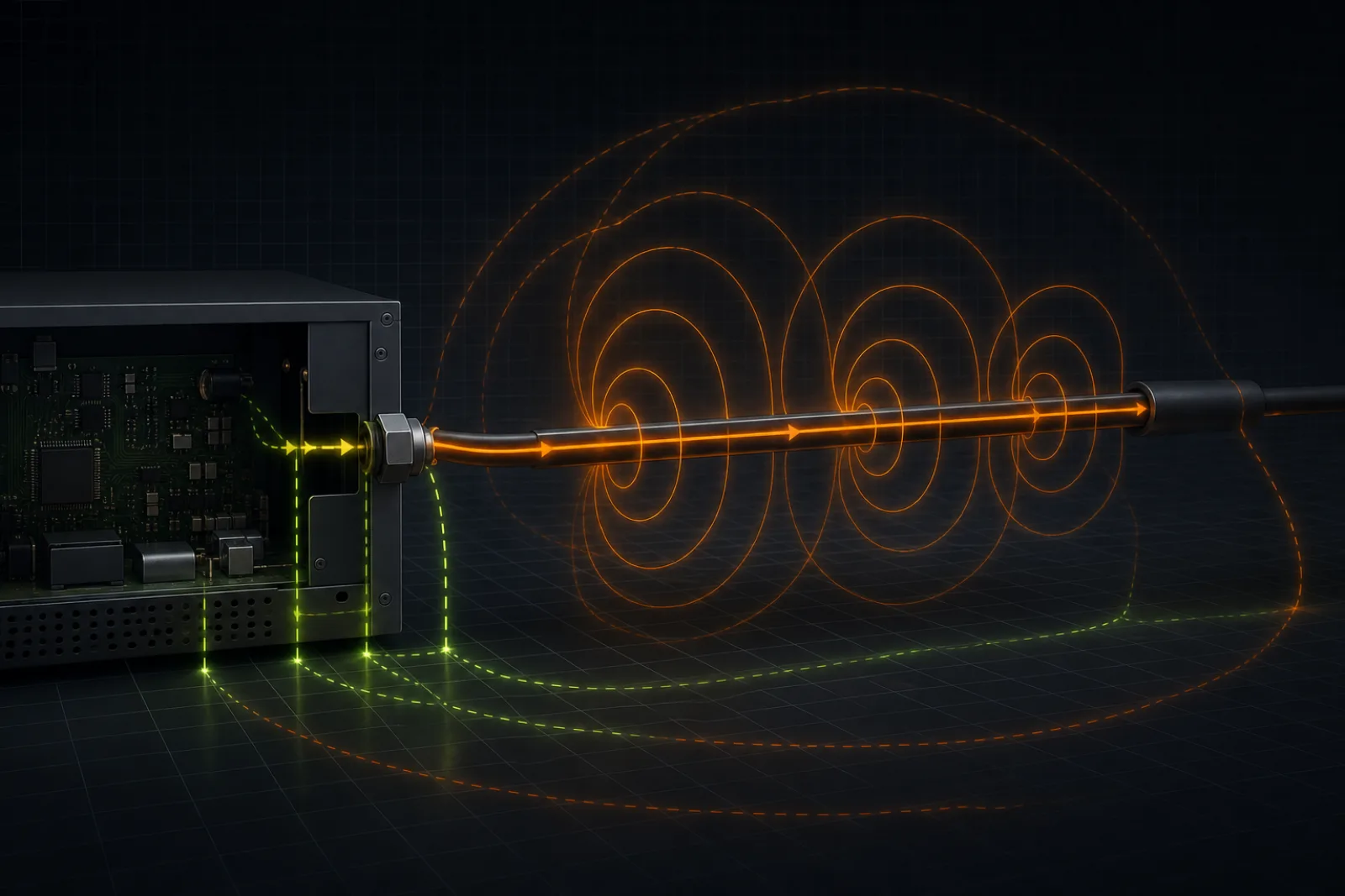
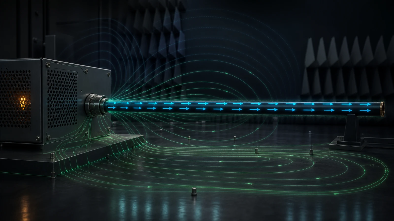
机壳线缆上的共模电流、辐射场和分布式环境返回路径概念图Conceptual illustration · not simulation · AI-assisted technical review complete
D05 / Design paths

Cable common-mode current drives radiation

In-phase current flows on the external cable and returns through enclosure capacitance and the surrounding environment.

BoundaryCable length changes conversion efficiency but does not create common-mode excitation.
07 / CONCEPT MAP

Six engineering lessons turn fundamentals into design actions.

Each conclusion states its boundary so that laboratory experience does not become a universal rule for every product.

01λ = c / f

The near field is not a smaller far field

Close to a source, the E/H ratio depends on source geometry. Only in the far field do E, H and propagation direction settle into a stable relationship.

Boundary
The near-/far-field boundary depends on wavelength, radiator size and distance; it cannot be defined by one fixed number of centimetres.
Engineering action
Use near-field probes for board-level localization, then return to the specified antenna, distance and site for compliance conclusions.
Rohde & Schwarz · Near-field probe fundamentalsTektronix · Three-step EMI troubleshooting
02H ↔ di/dt · E ↔ dv/dt

What E-field and H-field probes actually detect

H-field loops are most useful for tracing high-frequency current loops; E-field probes respond more strongly to high-dv/dt nodes, apertures and floating metal.

Boundary
Uncalibrated near-field probes provide relative localization, not compliance field strength. Smaller probes improve spatial resolution but usually reduce sensitivity.
Engineering action
Start with a large probe, refine with a smaller one, rotate the H probe to confirm flux orientation, and keep the probe height fixed.
Tektronix · EMI troubleshootingRohde & Schwarz · Choosing a near-field probe
03Lq ≈ VF · λ / 4

Why a cable becomes an antenna

A cable radiates efficiently only when common-mode current and a return path exist. An odd quarter-wave length indicates geometric sensitivity, not automatic failure.

Boundary
Termination, enclosure, connector, cable placement and nearby materials shift the real resonance; length alone cannot predict a limit exceedance.
Engineering action
Correlate cable common-mode current with the far-field peak, then vary cable length, placement or a clamp ferrite to test the hypothesis.
Murata · Conductor conduction and common modeTexas Instruments · Ethernet radiated emissions
04Icm = (I+ + I−) / 2

How differential mode converts to common mode

Ideal differential currents partly cancel in the far field. Asymmetry in drivers, traces, vias, connectors, termination or references creates net common-mode current.

Boundary
Allowable intra-pair skew depends on interface timing, loss and receiver tolerance; no universal 5-mil rule applies to every interface.
Engineering action
Control symmetry and reference continuity across the full channel before adding a common-mode choke, then verify its mixed-mode S-parameters.
Texas Instruments · Differential connectionsMurata · Differential transmission noise suppression
05Sensitive scale ≈ λ / 2

The longest aperture dimension matters more than area

A long slot interrupts enclosure surface current and can form a slot antenna. For equal airflow area, arrays of small holes are usually preferable to one long slot.

Boundary
Shielding also depends on slot orientation, polarization, wall thickness, seam impedance and source position; this model shows geometry sensitivity only.
Engineering action
Shorten continuous seams and improve RF contact; for ventilation, prefer small-hole arrays or below-cutoff waveguide structures.
NASA · Shielding design guidelinesWürth Elektronik · EMC shielding practical guide
06VL = L · di/dt

Shield termination is a high-frequency return-path design

A 360° bond gives shield current a low-inductance transition. A pigtail adds series inductance and develops RF voltage between shield and enclosure.

Boundary
Shield bonding must also satisfy safety, low-frequency loop, isolation and interface constraints; single- versus multi-point bonding is a system decision.
Engineering action
Bond the shield short, wide and circumferentially at the enclosure entry; complete filter return paths at the same penetration boundary.
Würth Elektronik · Gigabit Ethernet EMCNASA MEDIC · Bonding and grounding
08 / VISUAL ATLAS

See the structure before choosing the countermeasure.

Each visual isolates one critical path and is explicitly conceptual, preventing illustrative field lines from being mistaken for quantitative simulation.

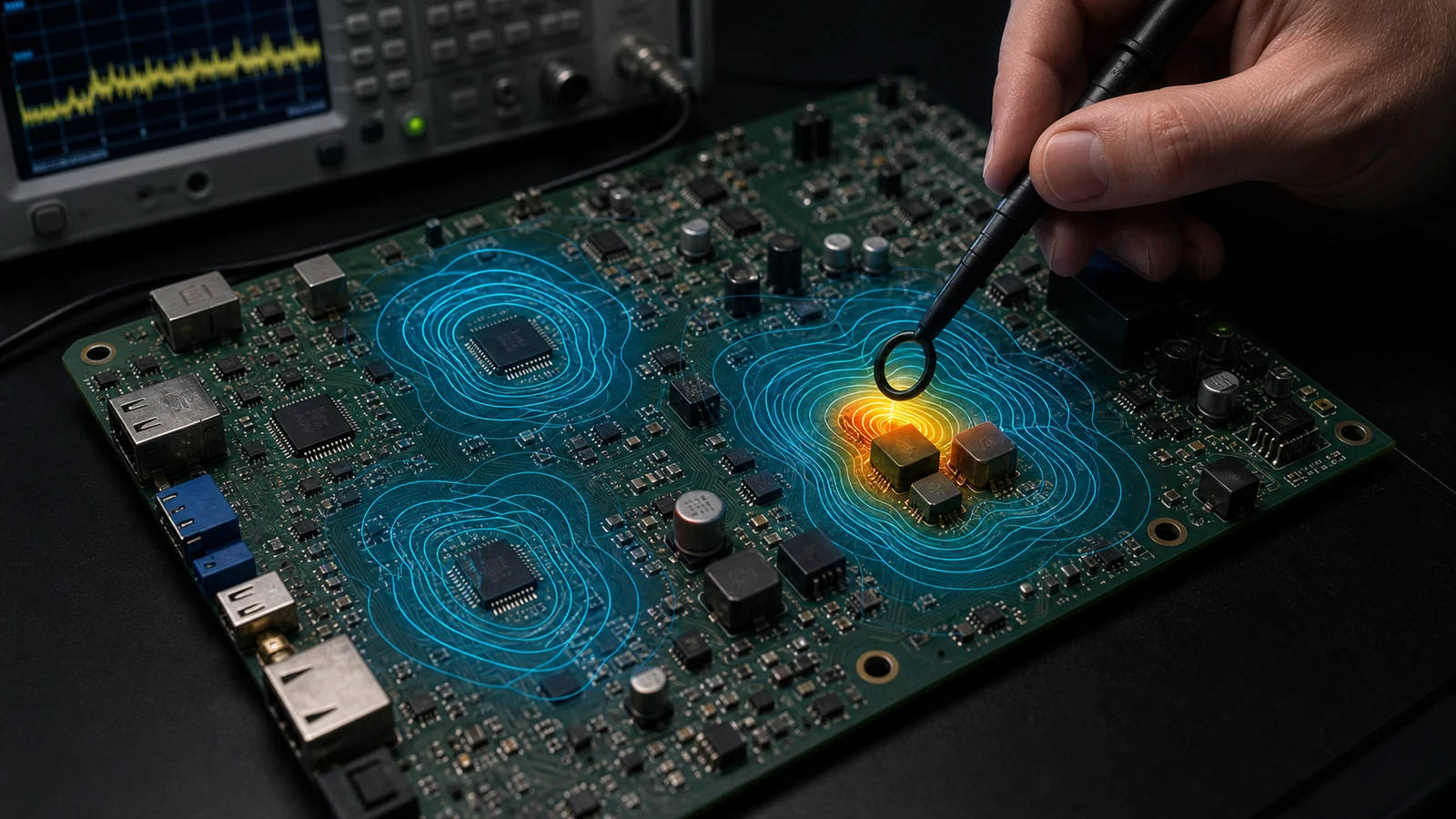
H 场环路探头扫描 PCB 上局部电流回路的概念图Conceptual illustration · not simulation · AI-assisted technical review complete
VISUAL 01

Near-field scanning is not a search for the brightest colour

Hold distance, orientation and RBW constant; find relative hot spots first, then correlate them with frequency and operating mode.

差分电流经过不对称连接器后出现线缆共模分量的概念图Conceptual illustration · not simulation · AI-assisted technical review complete
VISUAL 02

Asymmetry converts differential mode into common mode

Asymmetry in drivers, routing, connectors and parasitic returns leaves an in-phase current component on the cable.

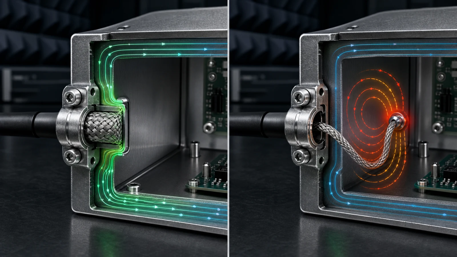
360度屏蔽端接与长尾线端接的对比概念图Conceptual illustration · not simulation · AI-assisted technical review complete
VISUAL 03

A shield termination is part of the RF return path

A 360° bond preserves surface-current continuity; pigtail inductance raises RF voltage between the shield and enclosure.

09 / VISIBLE CHANGE

Probe motion and peak changes make source correlation visible.

Probe position, hot-spot intensity, trace and meter change together, so the result does not depend on interpreting a subtle colour shift.

NEAR-FIELD SCAN / SOURCE CORRELATION

Make the change obvious as the probe crosses a hot spot.

The high-di/dt input hot loop produces a local magnetic field; probe output rises clearly as it crosses the loop.

外部线缆上共模电流与四分之一波长几何敏感度概念图COMMON-MODE / CABLE GEOMETRYConceptual illustration · not simulation · AI-assisted technical review complete
10 / CABLE AS ANTENNA

A cable is not inherently an antenna; common-mode current is the drive.

A differential link may appear closed yet still produce net common-mode current through driver imbalance, connector parasitics, enclosure voltage or shared impedance. Cable length only changes how efficiently that energy reaches the far field.

  • Confirm high-frequency cable common-mode current with a current probe
  • Correlate it with the far-field peak, operating mode and harmonic relationship
  • Test one variable at a time: cable, termination, common-mode path or shield bond
11 / CABLE RESONANCE

Vary cable length to inspect geometric sensitivity.

This model shows proximity to an odd quarter wavelength; it does not invent a pass probability or radiation level in dB.

COMMON-MODE CABLE / GEOMETRY

Near-resonant length does not guarantee radiation.

The model only checks whether cable geometry approaches an odd quarter wavelength. Radiation still requires common-mode excitation, a closed return path and sufficiently low loss.

12 / SHIELD TERMINATION

Switch termination geometry to compare current continuity.

Geometry, colour, current flow and status change together, making the difference between a 360° bond and a pigtail explicit.

CABLE SHIELD / CURRENT CONTINUITY

For the same shielded cable, termination geometry changes the RF path.

A 360° circumferential bond transfers shield current to the enclosure surface with low inductance.

13 / SHIELD APERTURE

Preserve surface-current continuity—not merely metal coverage.

The central shielding question is whether RF surface current can cross seams, apertures and cable penetration boundaries.

SHIELD APERTURE / LONGEST DIMENSION

For equal aperture area, geometry changes the result.

The model compares the longest continuous aperture dimension with half a wavelength. It does not calculate shielding effectiveness in dB because polarization, surface-current direction, wall thickness, contact impedance and source position also matter.

14 / MYTH CORRECTION

Turn six common claims into testable questions.

Professional guidance is not a longer list of rules; it states when each rule holds and when it fails.

01

A low clock frequency means low EMI

Rise time, ringing and nonlinearity set high-frequency energy; measure the edge and spectrum first.

02

Ground is always 0 V

Ground is a conductor network with frequency-dependent impedance; draw the complete return current.

03

Differential traces do not radiate

Only the balanced differential component cancels; inspect mode conversion across the full channel.

04

A TVS prevents every ESD reset

The clamp, branch inductance, discharge reference and sensitive node jointly determine residual voltage.

05

A larger capacitor always filters RF better

Above self resonance, parasitic inductance dominates; use the real impedance curve.

06

A thicker shield is always better

Most RF leakage is controlled by seams, apertures and penetrations; trace surface current first.

15 / PROCESSED EVIDENCE

Global references become engineering actions before entering the course.

These are not unprocessed links. Each source is reduced to conclusions that change a design or measurement decision and aligned with the source–path–antenna–victim model.

NASA

MEDIC EMC design and interference-control handbook

Treat grounding, bonding, shielding and system return paths as architecture—not schematic symbols.

Check the primary source ↗
Rohde & Schwarz

Near-field probes and field-region fundamentals

The near-field E/H ratio depends on the source; near-field localization and far-field measurement serve different purposes.

Check the primary source ↗
Murata

Cable common-mode current and mode conversion

When imbalance breaks differential cancellation, net cable common-mode current can become the dominant radiation path.

Check the primary source ↗
Tektronix

Three-step EMI troubleshooting

Correlate three evidence classes: near-field source localization, cable-current paths and close-range antenna confirmation of actual radiation.

Check the primary source ↗
Würth Elektronik

Shielding and 360° cable termination

Pigtail inductance breaks high-frequency shield continuity; the mechanical connection is itself an EMC component.

Check the primary source ↗
Analog Devices

Continuous references and complete return paths

Do not assume a ground plane is zero volts everywhere; layout must trace the complete return path of every critical current.

Check the primary source ↗